
Small pressure disturbance cause the unstable airflow to tumble, and intermixing of the air particles takes places. As the airflow moves back from the leading edge, the boundary layer thickens and becomes unstable. Fluid particles in this region to not intermingle. This type of airflow is called laminar flow and is characterized by smooth regular streamlines. The beginning of airflow at the leading edge of a smooth airfoil surface produces a very thin layer of smooth airflow. The behavior of the boundary layer determines, in great measure, the maximum lift coefficient and the stalling characteristics of the airfoil. This layer of air, the particles that grab on to the wing completely to those that don't, is known as the boundary layer.
#Airfoil diagram skin#
As you get further away from the skin of the airfoil, the particles are less apt to "grab on" to the wing and at a certain distance they do not "grab on" at all. When an airfoil passes through an airstream, the particles of air right next to the skin of the airfoil are pulled along at the same speed of the airfoil. To understand airfoil performance at high angles of attack, one must first consider the airflow at just about any angle of attack. We have discussed stall AOA, but these facts are of equal importance: an aircraft has its maximum climb angle at a certain AOA, will achieve maximum rate of climb at another AOA, and will get maximum range at still another AOA. The importance of AOA in determining aircraft performance cannot be overemphasized.

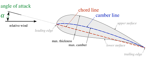
A symmetrical wing, on the other hand, produces less total lift but when it drops off, it drops off slowly. In the graph shown, we see that a typical cambered wing produces a higher coefficient of lift but when it gets to its critical angle of attack, the lift drops off quickly. We change the angle of attack using our flight controls and, in some cases, power settings.įor any given wing, an increase in angle of attack leads to an increase in the coefficient of lift up until the point it doesn't. We can change the shape of the wing using flaps, slats, or other similar leading and trailing edge devices. You can read further on airfoil aerodynamics in Part 4 of the Fundamentals of Aircraft Design Series.The coefficient of lift is a measure of how much lift the wing can produce and can only be changed by changing the shape of the wing or the angle of attack at which it cuts through the relative wind. Highly cambered airfoils produce more lift than lesser cambered airfoils, and an airfoil that has no camber is symmetrical upper and lower surface. The camber line is a line drawn equidistant between the upper and lower surface at all points along the chord. Camber is generally introduced to an airfoil to increase its maximum lift coefficient, which in turn decreases the stall speed of the aircraft. Figure 4: Typical timing diagram for PIV image acquisition. The final design parameter camber is a measure of the asymmetry between the upper and lower surface. Abstract A NACA 0015 airfoil with and without a Gurney flap was studied in a wind tunnel. This means that the thickest section has a height equal to 12% of the total chord. The airfoil plotted above has a thickness-to-chord ratio of 12%. The thickness of the airfoil is a very important design parameter and as always expressed as a percentage of the total chord. This often varies down the span of the wing as the wing tapers from the root to the tip.
#Airfoil diagram full size#
The SVG (Scalar Vector Graphics) plan can be printed out full size or over multiple pages for large sections. The camber, thickness can be adjusted and the pitch set to allow for wing angle of attack, wash out or wind turbine blade angle. The length of the airfoil from leading to trailing edge is known as the airfoil chord. Airfoil plotter View and plot a full size plan of the airfoil to your chord width. The airfoil upper and lower surfaces meet at the leading and trailing edges. The forward section of the airfoil is named the leading edge and the rear the trailing edge. The image below of a cross-section through a typical wing, shows a number of fundamental definitions associated with airfoil (aerofoil) nomenclature.


 0 kommentar(er)
